


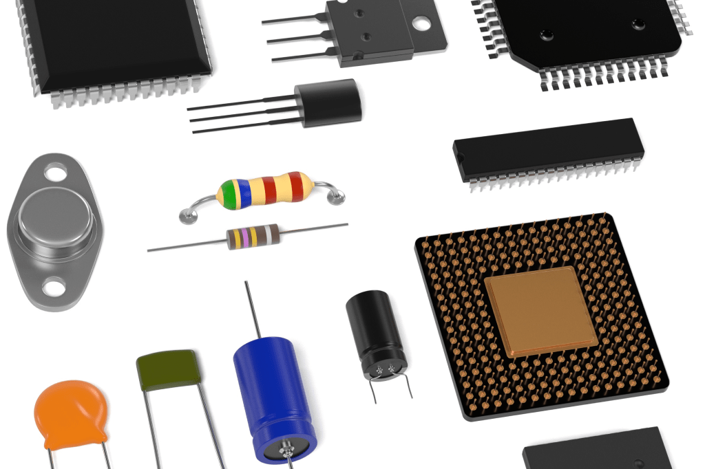
Surface-mount devices (SMDs) are widely used in electronic circuits, including compact designs. This article explains how to identify common SMD components and understand their main characteristics. Package appearance and markings are clues, but the bill of materials and manufacturer's datasheet are the reliable references.
What is an SMD?
SMD stands for surface-mount device. These components are designed to be mounted directly on the surface of printed circuit boards (PCBs), rather than using leads inserted through board holes. Many SMD packages are compact, helping save board space.
How can you recognise an SMD?
SMD components connect to pads on the board surface. In through-hole technology (THT), component leads pass through holes in the PCB.
Useful identification clues include:
- Package size: common chip sizes include 0603, 0805 and 1206. In the imperial naming system these codes describe approximate length and width in hundredths of an inch, not height. Metric codes also exist, so confirm the convention.
- Termination style: surface-mount packages may have metal end terminations, flat leads, pads underneath or solder balls. SMD does not mean every component has no leads.
- Markings: some parts use numeric or alphanumeric codes for values or identification. Very small parts may have no marking.
- Height: many SMD packages have a low profile, although height varies by device and package.
- Board position: surface-mount parts can be assembled on either or both sides of a board, depending on the design and process.
Marking systems vary. For example, in a common resistor value notation, R replaces the decimal point: R10 can mean 0.10 Ω, not 10 Ω. Always confirm the manufacturer's convention.
Letters such as C for capacitors and D for diodes often appear as reference designators on the PCB or schematic. They are different from the component's own package marking.
Main characteristics of SMD components
Typical characteristics include:
- Compact size: many surface-mount parts are smaller than comparable through-hole versions, supporting more compact circuits.
- High assembly density: suitable packages and layouts allow closely spaced components, within manufacturing and electrical limits.
- Low profile: many packages support thin or compact devices.
- Reliability: reliability depends on the component, operating conditions, layout and qualified assembly process, rather than the mounting style alone.
- Automated assembly: suitable SMD packages support automated placement and reflow soldering, improving repeatability and throughput.
- High-frequency applications: shorter interconnections can reduce some parasitic effects, which is useful in RF and high-speed circuits. Suitability still depends on the actual component and layout.
SMD is a package and mounting description, not a guarantee of low resistance or high power capacity. Mechanical and vibration performance also depend on the package, solder joints, board support and operating environment.
Which components are available in SMD packages?
Surface-mount technology (SMT) is the assembly method; SMD describes the component. Many electronic functions are available in packages intended for this method.
Examples include:
- SMD resistors : limit current, establish voltage relationships and perform other circuit functions.
- SMD capacitors: store electrical energy and support filtering, decoupling and timing.
- SMD diodes: conduct preferentially in one direction, with different diode types providing rectification, protection or light emission.
- SMD transistors: switch or amplify signals and control current.
- SMD jumpers: provide defined connections, often using zero-ohm links.
- SMD fuses: provide overcurrent protection within their specified ratings. They are not a general substitute for surge-voltage protection.
- SMD microcontrollers: combine processing, memory and peripherals for control functions.
- SMD integrated circuits: implement functions such as amplification, signal processing or motor control.
- SMD transformers: transfer energy or signals between windings in a suitable circuit.
The following sections explain useful identification checks for these components.
How can you identify SMD resistors?
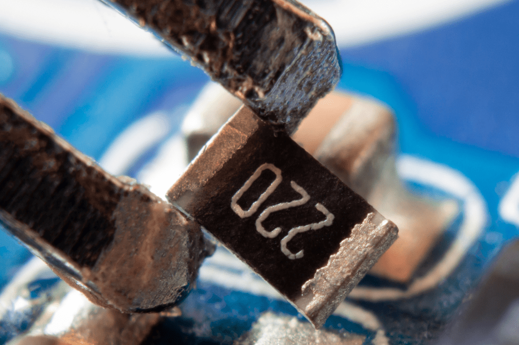
Check the following features:
- Height: chip resistors commonly have a low profile. Use the package drawing for the actual dimensions.
- Shape: many are rectangular, with conductive terminations at the two ends. Other constructions also exist.
- Value marking : many chip resistors use numbers or letters rather than the colour bands familiar from axial resistors. Small packages may be unmarked.
- Identification: a marking may indicate a value or manufacturer-specific code. Use the component documentation to interpret it.
- Termination spacing: compare the package dimensions and terminal arrangement with the specified PCB footprint.
Resistor markings may use several conventions. The following examples apply only to the relevant marking system.
- Resistance value : common schemes include three-digit, four-digit and coded markings, plus an R used as a decimal separator. In the common three-digit scheme, 330 means 33 × 10⁰ = 33 Ω, and 221 means 22 × 10¹ = 220 Ω. If a manufacturer uses J as a tolerance suffix, it commonly means ±5%. Colour-band rules apply to suitable resistor types, such as some MELF packages:
- The initial bands provide the significant digits
- The multiplier band determines the power-of-ten factor
- A separate tolerance band indicates the permitted variation
In a three-digit numeric code:
- The first two digits are significant digits
- The third digit is the power-of-ten multiplier
- Tolerance: where the applicable scheme uses these letters, common codes are F for ±1%, G for ±2%, J for ±5% and K for ±10%. Confirm the code against the datasheet.
How can you identify SMD capacitors?
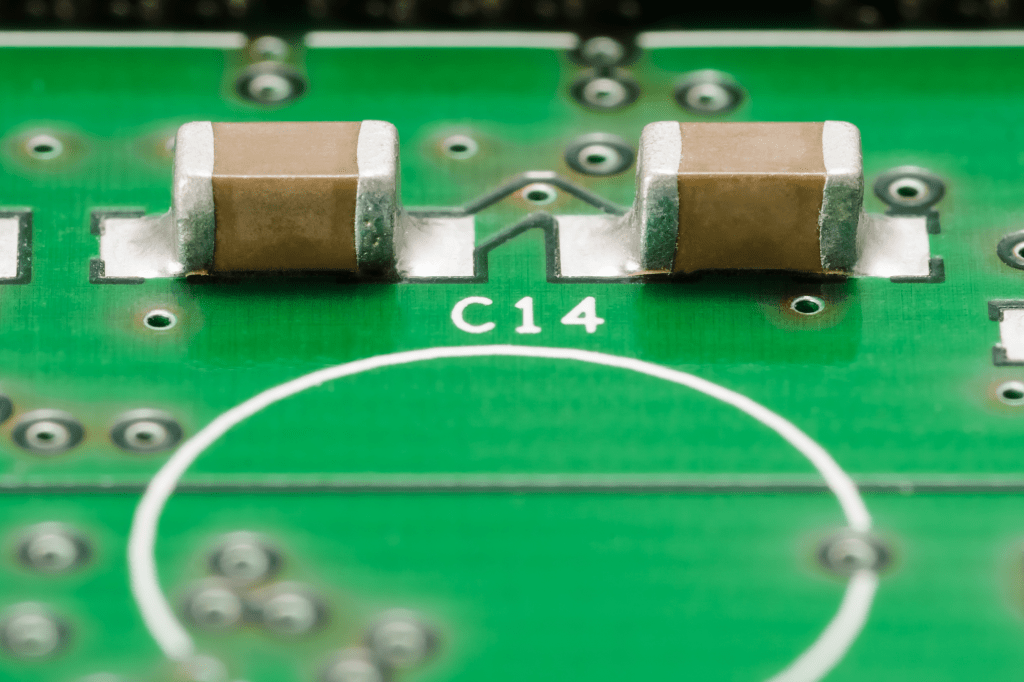
Capacitor packages vary widely. Useful checks include:
- Size: chip capacitors can be very small, while other SMD capacitor types use larger packages. Check the manufacturer's dimensions rather than assuming a universal size range.
- Polarity : ordinary multilayer ceramic capacitors are non-polarised. Many tantalum and aluminium electrolytic capacitors are polarised and must be fitted correctly.
- Value code : where a three-digit capacitance code is used in picofarads, 220 means 22 pF and 104 means 100,000 pF, or 100 nF. Many ceramic chips have no printed value.
- Manufacturer identification: any printed code must be checked against the manufacturer's scheme. A C on the board is usually a reference designator, not proof of the package type.
- Appearance : ceramic chips are often rectangular, while electrolytic and other capacitors can have different shapes.
These clues help narrow down the part type. If there is uncertainty, use the bill of materials, schematic and datasheet or ask the manufacturer.
What do capacitor letters and units mean?
Capacitance may be written with a number and unit prefix or encoded using a manufacturer's scheme. A separate letter may indicate tolerance.
For example, 10 nF ±5% describes a nominal capacitance of 10 nanofarads with a tolerance of five per cent.
Common prefixes are:
- p: pico, 10⁻¹² F
- n: nano, 10⁻⁹ F
- u or μ: micro, 10⁻⁶ F
- m: milli, 10⁻³ F
Examples:
- 100 pF means 100 picofarads.
- 1 uF means 1 microfarad.
- 10 mF means 10 millifarads.
What does uF mean?
uF is a common plain-text representation of µF, meaning microfarads. It is a capacitance unit, not an abbreviation for a tantalum capacitor type. Equivalent series resistance (ESR) is a separate electrical parameter.
For example, 10 µF and 16 V specify capacitance and voltage rating. A compact package code must be decoded using the manufacturer's documentation; there is no universal UF16V10 naming rule.
Does an SMD capacitor have polarity?
Some do and some do not. SMD describes how the component is mounted, not whether it is polarised. Ordinary ceramic chip capacitors are non-polarised, while many tantalum and aluminium electrolytic types are polarised.
Check the datasheet and the board's polarity indication. R, L, C or GND are not universal positive and negative capacitor-terminal codes.
Polarity markings vary: a stripe or symbol can identify a particular terminal according to the capacitor type and manufacturer. Do not assume that every stripe marks the same polarity.
How can you identify SMD diodes?
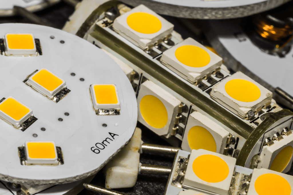
Useful steps include:
- Read the package marking and look it up in the manufacturer's data. The code may identify the device and package; a band may indicate the cathode in the specified package.
- Compare the package shape and dimensions. Many diode packages are small, but size alone does not distinguish a diode from another component.
- Use magnification to inspect the marking, orientation and any visible damage.
- Diodes include rectifier, signal, Zener, Schottky, LED and protection types. Their electrical behaviour differs. These types have different functions and characteristics; use the part number, schematic and datasheet to identify the device.
How do you read transistor markings?
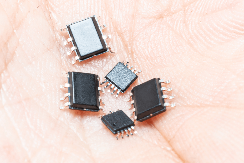
Transistor part numbers and short package codes vary by naming system and manufacturer. BC547B is an example of a full transistor number, but the familiar BC547 is a through-hole device, so it should not be used as evidence that a part is SMD.
- In an established numbering system, a prefix may identify a material or device category. Do not infer the detailed specification from one letter alone.
Check these points:
- The full part number
- The semiconductor and device type specified in the datasheet
- The package variant
- The manufacturer's marking table
- Subsequent characters may identify the device family, selection or variant.
Confirm the intended function:
- Small-signal amplification
- Power switching or amplification
- High-frequency operation where specified
- Electrical parameters must be read from the datasheet rather than decoded directly from the serial digits:
- Maximum collector-emitter voltage
- Maximum collector current
- DC current gain and its test conditions
- Frequency characteristics
- A final suffix may indicate a gain group, package, qualification or other variant. Its meaning depends on the device; for BC547B, B denotes a gain selection.
Use the exact manufacturer's datasheet and marking information. Short SMD codes may be shared by several different devices, so package and circuit context matter.
How do you distinguish NPN and PNP transistors?
The names describe the polarity of the semiconductor regions in bipolar junction transistors. The internal structure is not normally visible from the package.
For an NPN device, the simplified region sequence is:
- N-type emitter
- P-type base
- N-type collector
For a PNP device:
- P-type emitter
- N-type base
- P-type collector
Do not identify NPN versus PNP from a supposed universal pin order. Both types can use different pinouts. Check the part number and datasheet; suitable diode-test measurements can help assess junction polarity when the circuit conditions are understood.
How can you identify SMD jumpers?
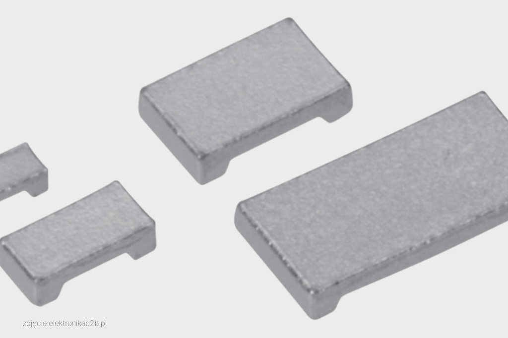
Useful checks include:
- Height: many surface-mount links have a low profile, but use the package specification.
- Shape: a zero-ohm chip link may resemble a resistor, with terminations at its ends. Other jumper constructions also exist.
- Markings : a zero-ohm resistor may be marked 0 or 000, or may be unmarked. Confirm the bill of materials and datasheet.
- Termination spacing : compare the part dimensions and footprint with the board documentation.
How can you identify SMD fuses?
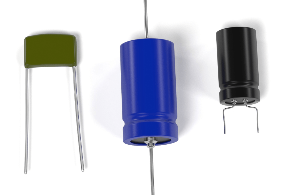
Surface-mount fuses have different package styles. Check their part number and ratings rather than relying only on appearance.
- Size: package designations can include imperial 0603 or 1206, but the manufacturer's drawing defines the actual dimensions and tolerances.
- Supply format: many are supplied in tape-and-reel packaging for automated placement.
- Markings: a manufacturer-specific code may indicate the part or current rating. Voltage rating, interrupting rating and time-current behaviour must be checked separately.
Useful information to confirm includes:
- Rated current in amperes
- Rated voltage
- Fast-acting behaviour where specified
- Time-delay behaviour where specified
How can you identify SMD microcontrollers?
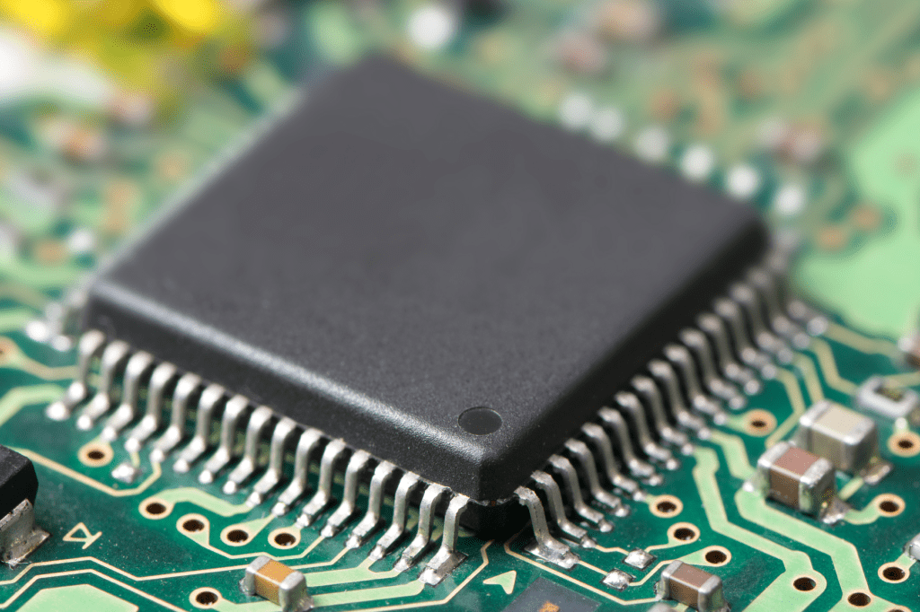
Check the device number and the exact package option:
- Size: package dimensions vary widely. Examples include small square packages and larger flat packages.
- Pin count: SMD microcontrollers may have a few pins or many dozens or hundreds. Surface mounting does not imply a lower pin count than through-hole devices.
- Supply format: parts may come in tape, trays or tubes, depending on the package and order code.
- Markings : identify the manufacturer and device code, then check the package marking against the datasheet.
Examples to look up:
- ATmega328P: an AVR microcontroller available in different package options, including surface-mount and through-hole variants.
- STM32F103C8T6: an STM32 microcontroller in a 48-pin LQFP package.
How can you identify other SMD integrated circuits?
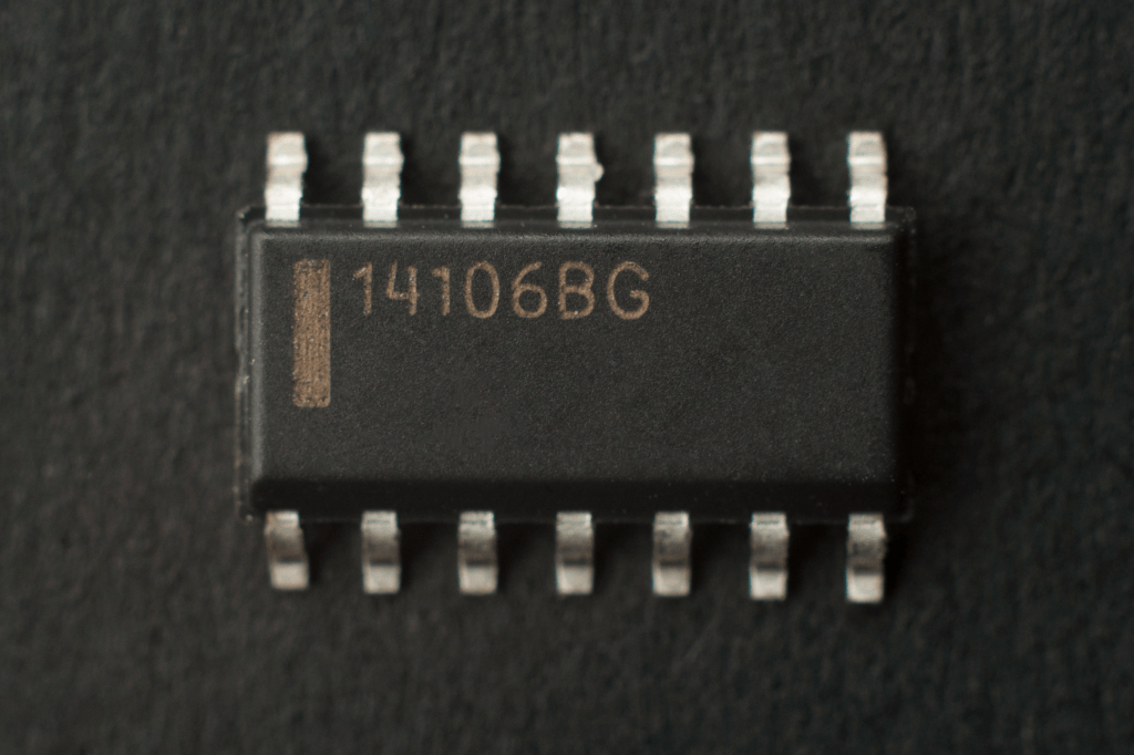
Use the exact ordering code and package drawing. Common checks include:
- Size: many packages are compact, but dimensions alone do not establish their function.
- Pin count: integrated circuits range from small packages with a few connections to large packages with many terminals or solder balls.
- Supply format : tape-and-reel, trays or tubes may be used depending on the package.
- Markings: a full or shortened code can identify the device when checked against the manufacturer's marking information.
Examples include:
- LM324: an operational-amplifier family offered in different package options; check the exact ordering code.
- ATtiny85: an AVR microcontroller available in package variants, so the family name alone does not establish the mounting method.
How can you identify SMD transformers?
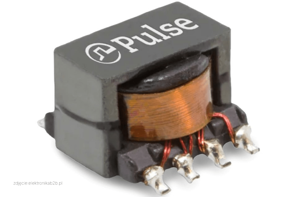
Surface-mount transformers are magnetic components designed for attachment to board-surface pads. They may be rectangular or square, but their dimensions and terminal arrangements depend on the construction.
Applications include suitable switching power supplies, converters and signal interfaces. A transformer can provide galvanic isolation when its winding arrangement, insulation and ratings support that requirement.
Select the part around parameters such as turns ratio, inductance, operating frequency, current, insulation and temperature. Package markings are usually manufacturer-specific.
Important parameters include:
- Inductance: winding inductance may be specified in microhenries (µH) or millihenries (mH). A code such as L100 cannot be interpreted universally without the manufacturer's information.
- Voltage and insulation ratings: these depend on the design and applicable test conditions. A supposed VAC250 marking is not a universal transformer-rating code.
- Current rating: allowable winding current depends on the specified electrical and thermal conditions. Do not assume that a marking such as I3.5 is used or means the same thing across manufacturers.
Use the datasheet for all of these parameters, including any insulation or safety approvals required by the application.
Identifying SMD components: conclusion
Package features and markings help identify surface-mount parts, but production requires an exact bill of materials and correct footprints. For SMT assembly, verify part numbers, package variants, polarity and orientation before release.
If you need help assessing components and assembly methods to improve manufacturing efficiency, arrange a manufacturability discussion. Our team can review the documentation and identify assembly considerations for your project.
Follow the link to arrange a PCB manufacturability consultation